IFS
Linear
What is IFS Linear?
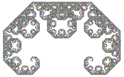
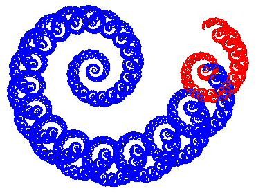
IFS Linear is a program for creating cool graphics like the
ones you
see above. Though you don't need to know it in order to use
the program, the cool graphics it produces are actually iterated
function system (IFS) fractals. That's where it gets the
"IFS"
part of its name.
How do you use IFS
Linear?
- Basic Usage
- Circle tools
- Rendering
- Tips
- The Koch curve
- Location
1. Basic usage
a. Circle tools
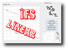
When the applet starts up, you should see a gridded design
area. That grid is where you will design your fractal. No time like the
present to experiment a little. Click the "Add Point" button. You
should see a circle tool appear in the center of the design area. Click
and drag the circle out of the center. Then click the "Add Point"
button again. Drag the new circle out of the center as well, and click
the "Add Point" button a third time. Now you have enough circles in
order to make a fractal. There may or may not be anything showing in
the preview area at this point. It depends on whether the distance
between the first and last points is greater than the lengths of all
the line segments or not (as illustrated below).
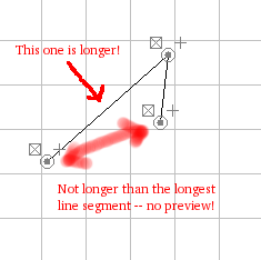

If you do not see a fractal in the preview area, drag one of
the
endpoints around until you do. You may also add a fourth point or even
more points. But no matter how many points you have, the distance
between the first and last has to be greater than the length of every
line segment. This table summarizes what you can do with circle tools.
 |
Translate
Tool
Use this tool to move the circle. |
 |
Flip
Sides Tool
The copy given by a line segment is flipped across the segment. |
 |
Reverse
Direction Tool
The copy given by a line segment is toggled between forward and
backward. |
 |
Delete
Tool
Use this tool to delete the circle. |
Clicking the "Restart" button erases all circle tools. It's
sort of a "start over" button.
Clicking "Snap to Grid" makes circle tools "snap" from one
location
to another as you drag them around. With "snap" on, the circle tools
can only be placed in limited locations. This is useful if you want to
place circles exactly on grid crossings or half-way points. Notice that
when you click the button, it turns into a "Freehand" button. Clicking
the "Freehand" button removes "snapping."
b. Rendering
When you like what you see in the preview area, you might want
to
click on the "Render Fractal" button. This will bring up a dialog box
that allows you to create a larger, more colorful version of your
fractal! Horns was rendered using the Random method; Lightning was
rendered with the single color method; Spiral was
rendered with the one color per map method; and Koch was rendered
with the deterministic method. Feel free to try them all, but be
careful with the deterministic method. It's not a mistake that the
number of iterations is small. It takes a long time to do each
iteration, and not very many are needed to create interesting
renderings.
2. Tips
a. The Koch Curve
You can make the Classic Koch curve several different ways.
Two of them are shown below.
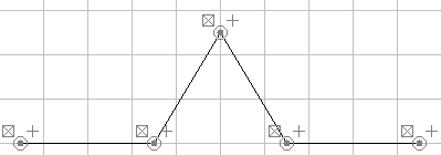
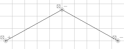
Notice the minus signs in the second one! Actually, neither
one of
these is exactly the Koch curve because the peak is just slightly off
in each one. But it's the best you can do with "snap" on. With snap
off, you can get a little closer, but still never hit it exactly since
the peak would need to be located at a point with an irrational
y-coordinate. That's never going to happen!
b. Location
As stated before, the first and last points must be a distance
away
from one another that is greater than the length of any line segment
you see! This is easiest is you spread the first and last points as far
from one another as you can for the given shape you are trying to
create.
What are .lifs files?
The .lifs
files hold
the mathematical description of your IFS fractal! It may or may not
interest you, but this is how IFS Freestyle sees the shapes in the
design area. Also, if you download the stand-alone
version, you will get save and open buttons so you can save
and retrieve your work. The .lifs
file is what is saved and read during these operations. A line like
Julia:-1.458647e+00,-1.408521e+00,false
is the mathematical description for the complex number mapping

where the plus or minus is
chosen
according to whether or not the last parameter is "true" or "false."
True means positive and false means negative.
However,
Linear IFS just uses this information to save the locations of the
points and whether they are positive or negative. It does not use this
interpretation at all (IFS Julia does)! Click "Show IFS Code" to see
the actual IFS Code. You will see lines like this:
AffineMap:(
0.5014 , 0.2798 , 0.2798 , -0.5014 , -0.6737 , -0.6975 )
This stands for the
transformation

Each one of these
transformations is a
similitude that maps the baseline (the imaginary line segment
connecting the first and last points) to one of the line segments in
your generator.
This page is hosted by 

